


Brickfête Ottawa 2014
10/10/14 12:33 Filed in: News

Brickfête is Canada's biggest AFOL show and is typically hosted annually in Toronto. Recently, Brickfête has added an additional "On the Road" show (starting with Montreal last year). This year, my home town of Ottawa was nominated as the next On the Road AFOL show.
Therefore, we AFOLs based in Ottawa have to make sure this is a rocking event! Despite the tight timeframe, transport logistics, etc. I'm going to bring my Fareham Lego model railway. I've started to put the layout together again in the basement and will be rebuilding damaged sections as well as adding a few new features. More rolling stock is planned as well as some other audio/video features :)
If you want to see my layout live, perhaps run some of your visiting rolling stock on the layout, and if you're in driving distance of Ottawa, Canada--come out and visit--better yet, if you're an AFOL, sign up to participate for the entire event! Visit www.brickfete.com for details!
The Building of Fareham Part 1 - Planning
07/10/14 21:45 Filed in: Information
Starting in 2003, I started a project to build a model railway based on Fareham station in Hampshire in the UK. I originally intended to build this layout as a OO gauge model railway which would be modular and incorporate many sophisticated design features such as layout automation, curved baseboards and photo-real texture scenery. I chose Fareham because I have a nostalgic connection to the British Rail Southern Region and because the station at Fareham incorporates several unique features which would make an interesting model. Looking back, I could have never predicted that this layout would eventually get built in LEGO® bricks! Although not as detailed and extensive as the OO gauge layout would have been, the LEGO® version still incorporates the essential design elements and the same sensibility towards prototype model railway fidelity.
This series of blog articles will document this layout’s design and construction. The process starts with research and information gathering, and then followed by planning. The planning process not only involves the essential track plan, but also key factors like the electrical design and supporting framework. Time taken at this crucial stage pays off dramatically during construction. At some point shortly after designing the OO gauge layout and starting construction, I became very involved in the LEGO® hobby. After building several LEGO® model trains and a few diorama set pieces for public display, I came to the crucial realization that I could in fact make a suitable representation of Fareham station in LEGO® brick instead. At this point, I effectively had to redesign the layout. However, I discovered that much of the design work performed for the OO gauge layout could in fact be adapted to the LEGO® version.
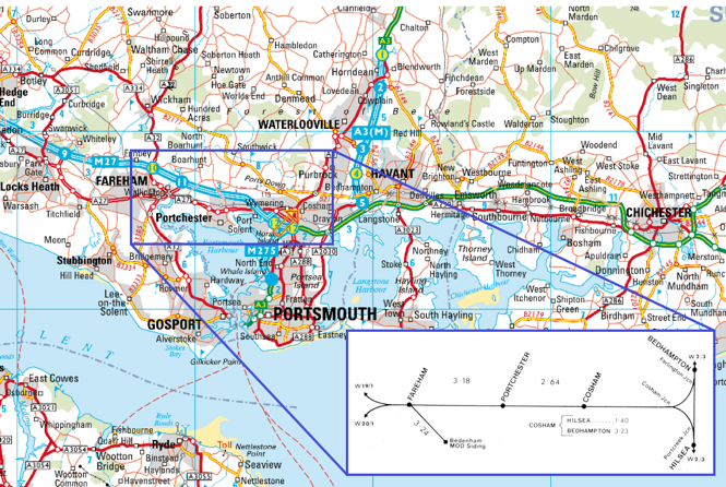
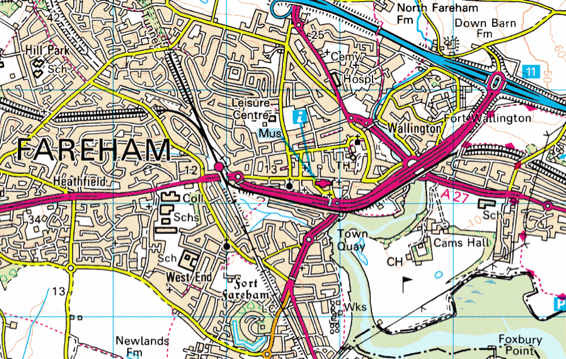
I started to compile background research photos and maps to start the planning process. Below are some of the materials I had acquired from various sources to aid with the plan:
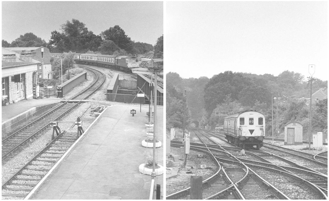
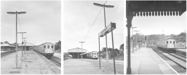
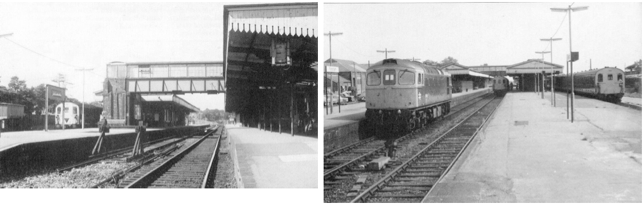
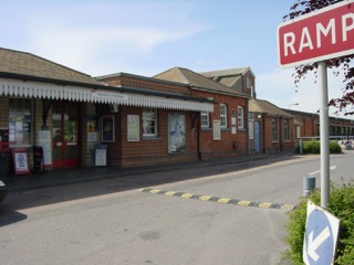
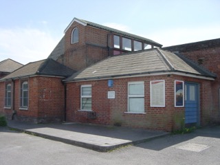
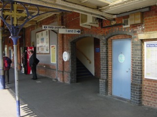
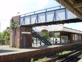
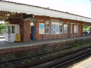
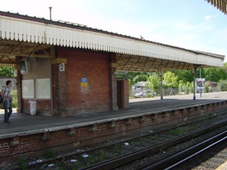
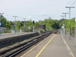
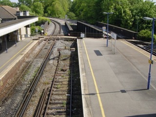
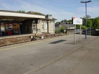
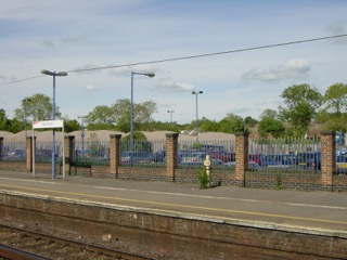
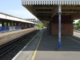
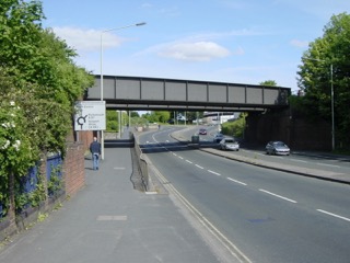
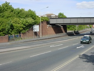
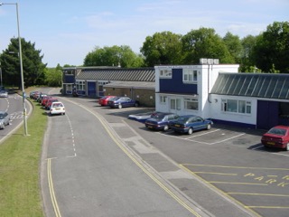
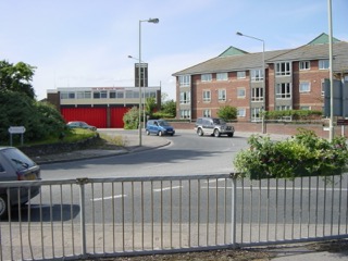
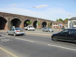
During the summer of 2003 I had the opportunity to visit the UK and I made a point to visit and extensively photograph Fareham station. I took dozens of photos of not just the station but also of the surrounding area. I wanted to capture distinguishing land features, buildings, bridges, etc. which I could incorporate into the layout. These photos would then serve as a useful guide to details when it came time to building the layout. Below is a sampling of some of my photographs:
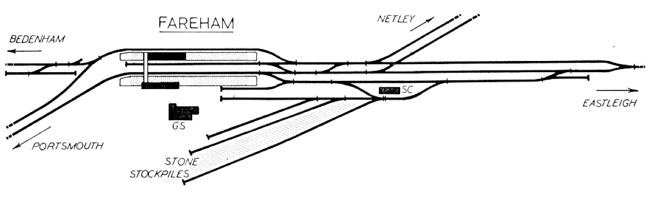
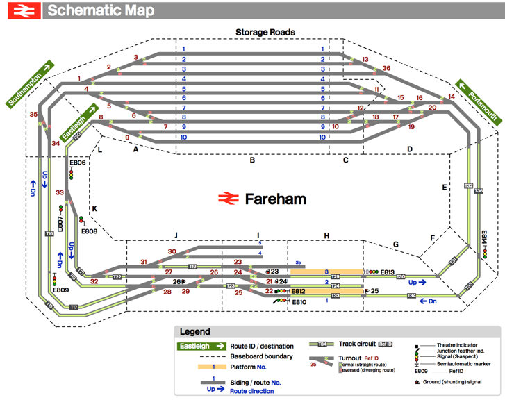
Before engaging in a detailed track plan to scale, I designed a layout schematic. This schematic shows the track arrangement geometrically from the point of view of operation. It documents routes, signal blocks, storage sidings, and track circuits. Also it breaks the layout down into modules labelled alphabetically (A, B, C, ...). These modules would represent the physical partition of layout baseboards as well as a prefix for electrical subassemblies contained with the module. Below is the layout schematic I had designed:
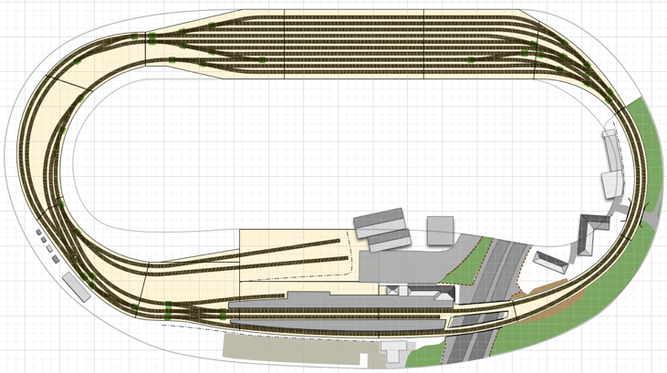
Based on this schematic representation, I then proceeded to design the layout using CAD tools. Specifically, XTrkCAD for the track diagram (using the Peco Code 75 Finescale track library) and OmniGraffle for the multi-layer composite drawing. The composite drawing was used to compile the entire layout design using different layers to represent key elements such the track, baseboard framework, scenery, electrical modules, etc. Below is the CAD design that I eventually converged to after many iterations:
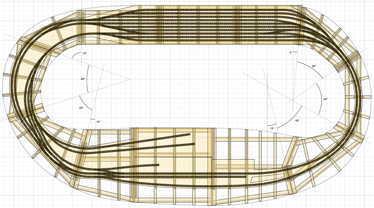
Here is the same drawing revealing the detailed design of the supporting L-girder timber framework baseboard design:
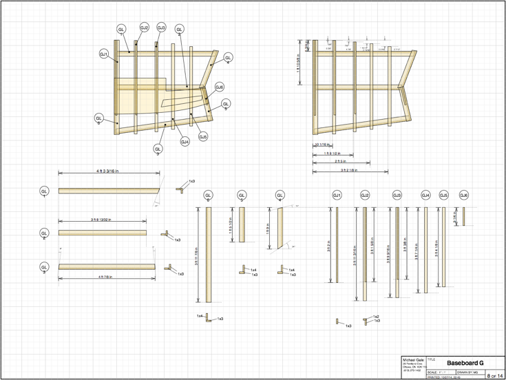
For each layout module, a detailed construction drawing was made such as the example shown below for module G representing the southern end of the station where the dual road bridges are located:
In the next instalment of this article series on Fareham station, I will discuss the electrical design of the layout control system. In particular, the use of NMRA DCC for train control and MERG C-Bus for layout control and automation.
This series of blog articles will document this layout’s design and construction. The process starts with research and information gathering, and then followed by planning. The planning process not only involves the essential track plan, but also key factors like the electrical design and supporting framework. Time taken at this crucial stage pays off dramatically during construction. At some point shortly after designing the OO gauge layout and starting construction, I became very involved in the LEGO® hobby. After building several LEGO® model trains and a few diorama set pieces for public display, I came to the crucial realization that I could in fact make a suitable representation of Fareham station in LEGO® brick instead. At this point, I effectively had to redesign the layout. However, I discovered that much of the design work performed for the OO gauge layout could in fact be adapted to the LEGO® version.
Research
I started to compile background research photos and maps to start the planning process. Below are some of the materials I had acquired from various sources to aid with the plan:
Maps
Track Diagram
Reference Photos
Site Survey
During the summer of 2003 I had the opportunity to visit the UK and I made a point to visit and extensively photograph Fareham station. I took dozens of photos of not just the station but also of the surrounding area. I wanted to capture distinguishing land features, buildings, bridges, etc. which I could incorporate into the layout. These photos would then serve as a useful guide to details when it came time to building the layout. Below is a sampling of some of my photographs:
Layout Design
Before engaging in a detailed track plan to scale, I designed a layout schematic. This schematic shows the track arrangement geometrically from the point of view of operation. It documents routes, signal blocks, storage sidings, and track circuits. Also it breaks the layout down into modules labelled alphabetically (A, B, C, ...). These modules would represent the physical partition of layout baseboards as well as a prefix for electrical subassemblies contained with the module. Below is the layout schematic I had designed:
Based on this schematic representation, I then proceeded to design the layout using CAD tools. Specifically, XTrkCAD for the track diagram (using the Peco Code 75 Finescale track library) and OmniGraffle for the multi-layer composite drawing. The composite drawing was used to compile the entire layout design using different layers to represent key elements such the track, baseboard framework, scenery, electrical modules, etc. Below is the CAD design that I eventually converged to after many iterations:
Here is the same drawing revealing the detailed design of the supporting L-girder timber framework baseboard design:
For each layout module, a detailed construction drawing was made such as the example shown below for module G representing the southern end of the station where the dual road bridges are located:
In the next instalment of this article series on Fareham station, I will discuss the electrical design of the layout control system. In particular, the use of NMRA DCC for train control and MERG C-Bus for layout control and automation.