DCC
Updated Layout Control Panel Using JMRI
22/04/15 18:17 Filed in: Information
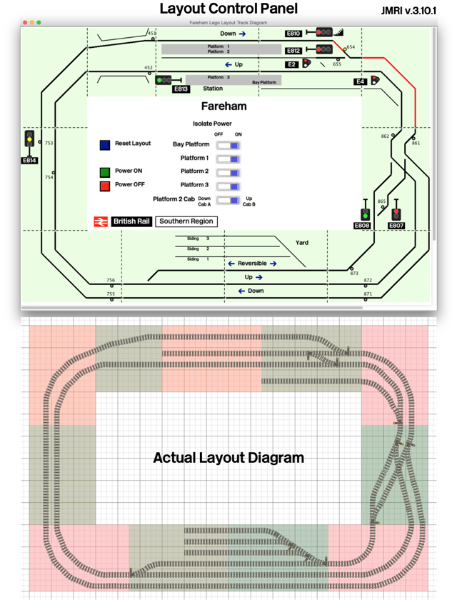
Here is an updated version of my layout's control panel implemented using JMRI, an open source model train software tool.
I have evolved this control system to include the full layout (including the yard switches) and more importantly to include "Train on Track" sensors. With these sensors, the signal system is now fully automated and interlocked. As a train passes a signal, it trips a sensor and the signal immediately changes to "Danger". The signal will progressively clear through "Caution" and "Proceed" aspects depending on the state of the signal blocks ahead.
Initially I was going to implement the train detection using a current feedback sensor on the power feeds to the track (similar to the prototype's track circuit). However, I wanted this system to operate with non metal/9V/DCC powered trains, i.e. battery/Power Functions trains. Therefore, I elected to use optical sensors embedded discretely in the track. The sensor consists of a 3mm phototransistor which is buried in a hole drilled within the ties. The sensor detects light being blocked by the presence of a train passing overhead. Each sensor is tunable to account for varying ambient light conditions depending on where the layout is setup.
The sensors as well as the actuators for the signals and turnouts are all connected using MERG's C-bus network. There are at least 16 different micro controllers lurking under the layout tables all communicating via C-bus to a central controller connected to my laptop PC via USB. The same central controller has an integrated DCC command station which drives the track power. Therefore, even the control of trains is achieved with the computer via virtual "throttles". It isn't too difficult to imagine the next step: complete automation of train operation! Well, not so fast, I still like to drive my trains too!
JMRI is a very powerful software suite of tools; however, it has a steep learning curve. For those of you with a technical interest, it is worth checking out.
New Concept for Train Control
26/02/15 10:21 Filed in: Ideas
I have been struggling with the issue of controlling Lego trains for quite some time. My layout has been built for operation with metal track and NMRA DCC control and my locomotives have been converted to run with DCC decoders attached to 9V motor bogies. However, I am worried about the future of 9V track/motors and have been bothered with the lack of performance of the 9V motor bogie.
Here are a few issues that I've been thinking about:
1) POWER - the 9V motor bogie is relatively weak and often a train requires 2x or more for sufficient traction
2) HYBRID DRIVE - I love not having to worry about batteries when operating my layout at a show. However, I like the flexibility of battery operation and for running on plastic track.
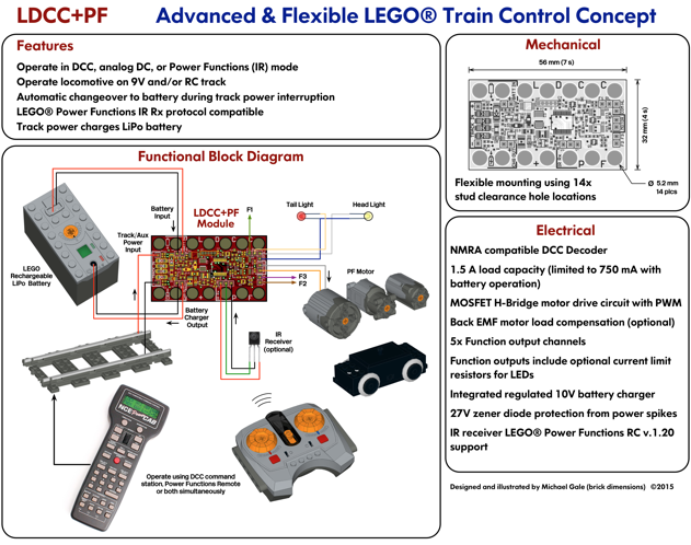
3) TECHNIC/PF CHASSIS - I have developed a few prototype locomotives where the chassis and body are completely separate. The chassis is mostly built from technic elements with an all-wheel drive train powered from a centrally located PF motor. The chassis is nominally 5-studs wide to allow for a 7-stud wide body. The all-wheel drive chassis I have built have amazing tractive effort--easily better than any 9V powered locomotive. They do run a bit slower, but its a prototypical speed which I prefer.
What you see illustrated above is a prototype electronic control module (which I have called LDCC+PF) which attempts to address some of the issues of train control. Effectively its a DCC decoder at its core. Unlike a DCC decoder it includes a battery/power management function and an IR receiver. Also, mechanically it is designed to fit with stud and/or technic pin attachments. This module attempts to combine the best features of DCC and Lego Power Functions. The goal is to have reliable, powerful, and flexible locomotive operation.
The idea is that the motor is always controlled using a smart DCC decoder. It will take commands from DCC encoded packets on the track and/or commands from the PF IR remote. It will extend the functionality of the PF remote by allowing for DCC standard 14/28/128 speed steps and interpreting button presses+channel selection for function control. In some ways, you could consider this module a functional replacement for the Lego PF IR receiver (obviously with tons of additional functionality!)
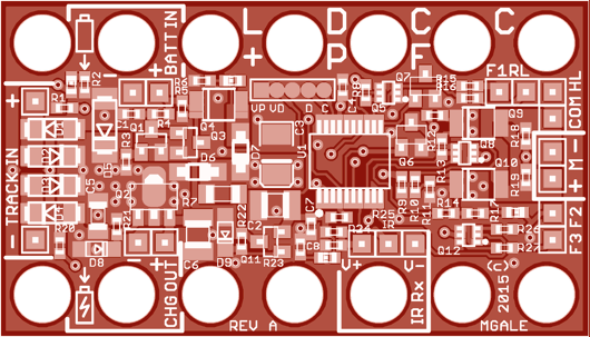
So far I have more-or-less completed the electrical design and printed circuit board (PCB) (shown below). I have fabricated the prototype PCBs and they are currently being tested. I have made a preliminary start on the firmware for the module's micro controller--but this will take a great deal of time. I do have a bit of a head start since I have based the DCC decoder design on MERG's DEC12 decoder. I am implementing totally new firmware on a different micro controller than the MERG design written in C rather than assembler. I also have to implement all of the Lego PF IR protocol in addition to the DCC.
I hope this experiment turns out--I do look forward to my ambition of a hybrid-drive train chassis!