Information
Heavy Metal
17/01/17 22:24
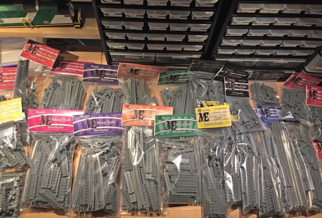
I'm not normally a fan of the "un-boxing" photo or video genre; however, I'll make an exception in this case!
After quite a long wait, I have finally received my much anticipated delivery of ME Models metal track elements.
It appears that the wait has been worth it. Initial exploration with assembling some track sections has put to rest any anxieties of adopting a novel, yet unconventional method of metalizing plastic track. Some observations:
1) The clutch power is much improved over previous ME track. The tendency for ballasted track sections to "explode" with any subtle twisting forces, resulted in me solvent welding the rails to the ballast plates.
2) Rail joints are smooth and seamless. This is not a surprise given that these are effectively HO/OO rail sections with fishplates. This will lead to very smooth running characteristics and superb electrical performance.
3) Nickel silver rail will resist corrosion and improve electrical performance.
4) Separate rail sections will broaden the opportunity to "scratch build" a wider variety of track. I've posted some track sections built to represent precast concrete rail-beds common with many high speed railway lines.
5) Flange way clearance is better without flanges running on the rail base.
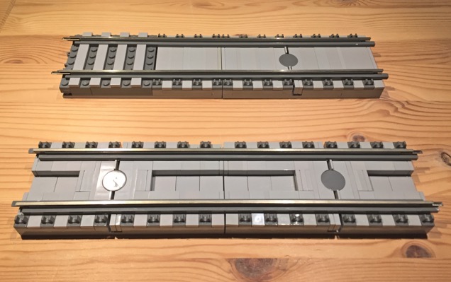
My only criticism is the possibility of creating uneven rail height during assembly. My initial tendency when assembling a rail section was to apply force on top of the rail head to secure it to the tie-plates. This would sometimes result in pushing the metal rail insert further into its groove resulting in uneven rail height. I now have to be conscious to apply force to the rail base flange rather than the rail head.
Overall, I say its a big win for us Lego train fans. The only remaining piece of the puzzle is motors with metal wheels!
Updated Layout Control Panel Using JMRI
22/04/15 18:17
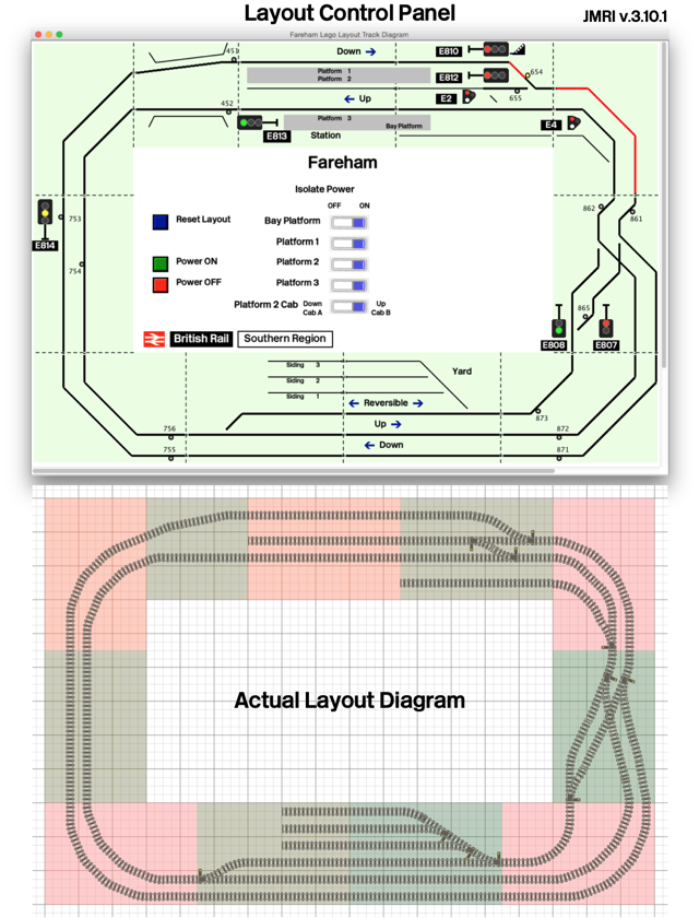
Here is an updated version of my layout's control panel implemented using JMRI, an open source model train software tool.
I have evolved this control system to include the full layout (including the yard switches) and more importantly to include "Train on Track" sensors. With these sensors, the signal system is now fully automated and interlocked. As a train passes a signal, it trips a sensor and the signal immediately changes to "Danger". The signal will progressively clear through "Caution" and "Proceed" aspects depending on the state of the signal blocks ahead.
Initially I was going to implement the train detection using a current feedback sensor on the power feeds to the track (similar to the prototype's track circuit). However, I wanted this system to operate with non metal/9V/DCC powered trains, i.e. battery/Power Functions trains. Therefore, I elected to use optical sensors embedded discretely in the track. The sensor consists of a 3mm phototransistor which is buried in a hole drilled within the ties. The sensor detects light being blocked by the presence of a train passing overhead. Each sensor is tunable to account for varying ambient light conditions depending on where the layout is setup.
The sensors as well as the actuators for the signals and turnouts are all connected using MERG's C-bus network. There are at least 16 different micro controllers lurking under the layout tables all communicating via C-bus to a central controller connected to my laptop PC via USB. The same central controller has an integrated DCC command station which drives the track power. Therefore, even the control of trains is achieved with the computer via virtual "throttles". It isn't too difficult to imagine the next step: complete automation of train operation! Well, not so fast, I still like to drive my trains too!
JMRI is a very powerful software suite of tools; however, it has a steep learning curve. For those of you with a technical interest, it is worth checking out.
The Building of Fareham Part 1 - Planning
07/10/14 21:45
Starting in 2003, I started a project to build a model railway based on Fareham station in Hampshire in the UK. I originally intended to build this layout as a OO gauge model railway which would be modular and incorporate many sophisticated design features such as layout automation, curved baseboards and photo-real texture scenery. I chose Fareham because I have a nostalgic connection to the British Rail Southern Region and because the station at Fareham incorporates several unique features which would make an interesting model. Looking back, I could have never predicted that this layout would eventually get built in LEGO® bricks! Although not as detailed and extensive as the OO gauge layout would have been, the LEGO® version still incorporates the essential design elements and the same sensibility towards prototype model railway fidelity.
This series of blog articles will document this layout’s design and construction. The process starts with research and information gathering, and then followed by planning. The planning process not only involves the essential track plan, but also key factors like the electrical design and supporting framework. Time taken at this crucial stage pays off dramatically during construction. At some point shortly after designing the OO gauge layout and starting construction, I became very involved in the LEGO® hobby. After building several LEGO® model trains and a few diorama set pieces for public display, I came to the crucial realization that I could in fact make a suitable representation of Fareham station in LEGO® brick instead. At this point, I effectively had to redesign the layout. However, I discovered that much of the design work performed for the OO gauge layout could in fact be adapted to the LEGO® version.
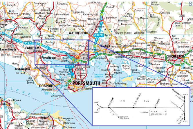
I started to compile background research photos and maps to start the planning process. Below are some of the materials I had acquired from various sources to aid with the plan:
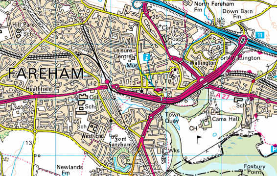

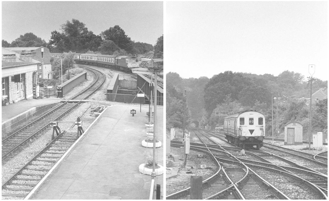
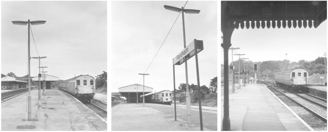

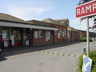
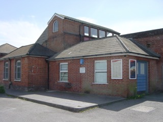
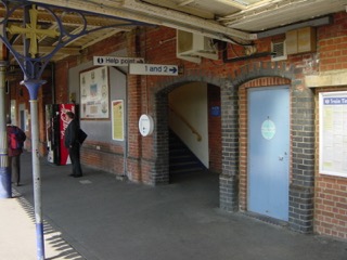
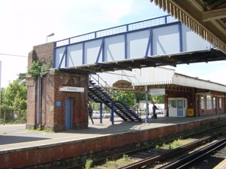
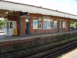
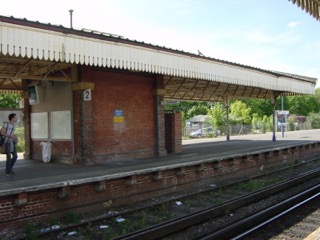
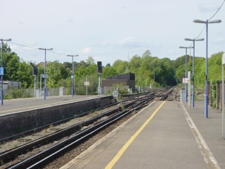
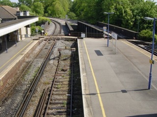
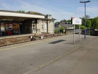
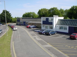
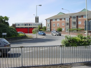
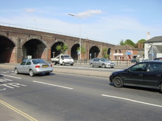
During the summer of 2003 I had the opportunity to visit the UK and I made a point to visit and extensively photograph Fareham station. I took dozens of photos of not just the station but also of the surrounding area. I wanted to capture distinguishing land features, buildings, bridges, etc. which I could incorporate into the layout. These photos would then serve as a useful guide to details when it came time to building the layout. Below is a sampling of some of my photographs:
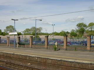
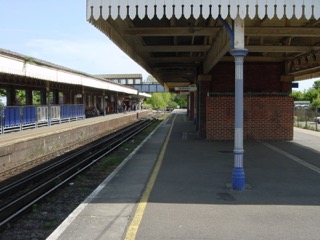
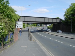
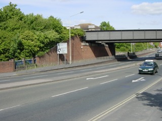
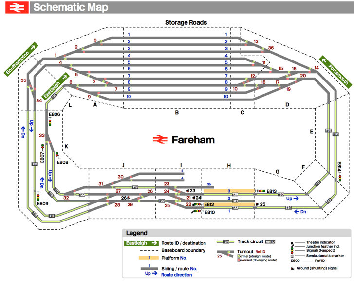
Before engaging in a detailed track plan to scale, I designed a layout schematic. This schematic shows the track arrangement geometrically from the point of view of operation. It documents routes, signal blocks, storage sidings, and track circuits. Also it breaks the layout down into modules labelled alphabetically (A, B, C, ...). These modules would represent the physical partition of layout baseboards as well as a prefix for electrical subassemblies contained with the module. Below is the layout schematic I had designed:
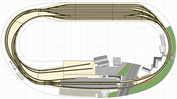
Based on this schematic representation, I then proceeded to design the layout using CAD tools. Specifically, XTrkCAD for the track diagram (using the Peco Code 75 Finescale track library) and OmniGraffle for the multi-layer composite drawing. The composite drawing was used to compile the entire layout design using different layers to represent key elements such the track, baseboard framework, scenery, electrical modules, etc. Below is the CAD design that I eventually converged to after many iterations:
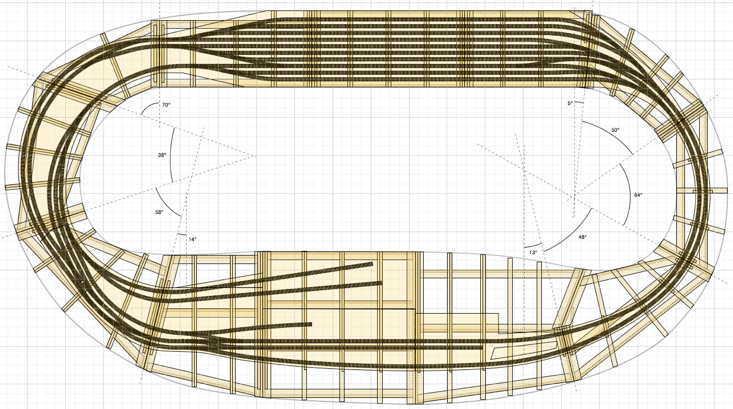
Here is the same drawing revealing the detailed design of the supporting L-girder timber framework baseboard design:
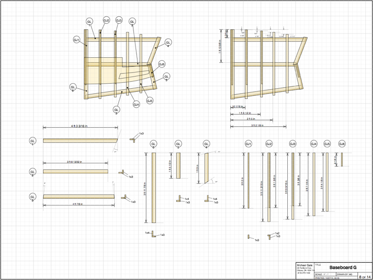
For each layout module, a detailed construction drawing was made such as the example shown below for module G representing the southern end of the station where the dual road bridges are located:
In the next instalment of this article series on Fareham station, I will discuss the electrical design of the layout control system. In particular, the use of NMRA DCC for train control and MERG C-Bus for layout control and automation.
This series of blog articles will document this layout’s design and construction. The process starts with research and information gathering, and then followed by planning. The planning process not only involves the essential track plan, but also key factors like the electrical design and supporting framework. Time taken at this crucial stage pays off dramatically during construction. At some point shortly after designing the OO gauge layout and starting construction, I became very involved in the LEGO® hobby. After building several LEGO® model trains and a few diorama set pieces for public display, I came to the crucial realization that I could in fact make a suitable representation of Fareham station in LEGO® brick instead. At this point, I effectively had to redesign the layout. However, I discovered that much of the design work performed for the OO gauge layout could in fact be adapted to the LEGO® version.
Research
I started to compile background research photos and maps to start the planning process. Below are some of the materials I had acquired from various sources to aid with the plan:
Maps


Track Diagram

Reference Photos


Site Survey
During the summer of 2003 I had the opportunity to visit the UK and I made a point to visit and extensively photograph Fareham station. I took dozens of photos of not just the station but also of the surrounding area. I wanted to capture distinguishing land features, buildings, bridges, etc. which I could incorporate into the layout. These photos would then serve as a useful guide to details when it came time to building the layout. Below is a sampling of some of my photographs:


Layout Design
Before engaging in a detailed track plan to scale, I designed a layout schematic. This schematic shows the track arrangement geometrically from the point of view of operation. It documents routes, signal blocks, storage sidings, and track circuits. Also it breaks the layout down into modules labelled alphabetically (A, B, C, ...). These modules would represent the physical partition of layout baseboards as well as a prefix for electrical subassemblies contained with the module. Below is the layout schematic I had designed:

Based on this schematic representation, I then proceeded to design the layout using CAD tools. Specifically, XTrkCAD for the track diagram (using the Peco Code 75 Finescale track library) and OmniGraffle for the multi-layer composite drawing. The composite drawing was used to compile the entire layout design using different layers to represent key elements such the track, baseboard framework, scenery, electrical modules, etc. Below is the CAD design that I eventually converged to after many iterations:

Here is the same drawing revealing the detailed design of the supporting L-girder timber framework baseboard design:

For each layout module, a detailed construction drawing was made such as the example shown below for module G representing the southern end of the station where the dual road bridges are located:

In the next instalment of this article series on Fareham station, I will discuss the electrical design of the layout control system. In particular, the use of NMRA DCC for train control and MERG C-Bus for layout control and automation.